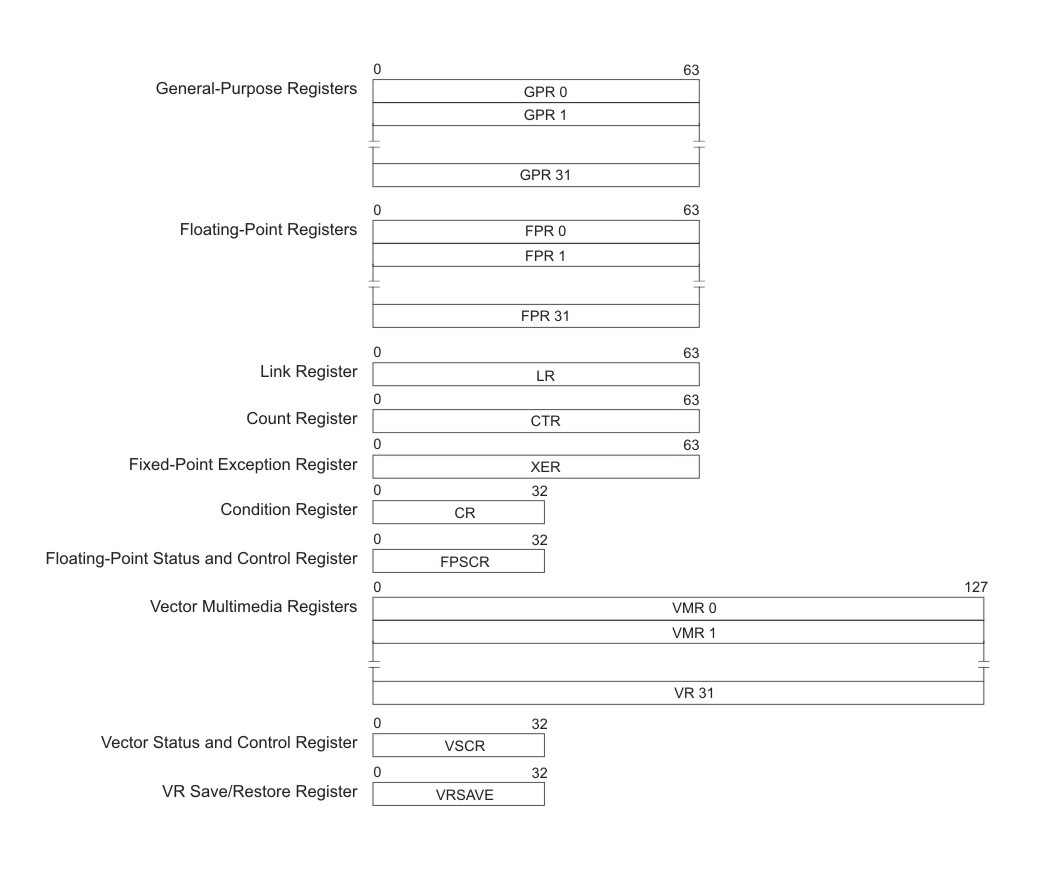
This section describes the complete set of PowerPC Processor Element (PPE) user (problem-state) registers.
Figure 1 shows all the PPE user (problem-state) registers. All computational instructions operate only on registers – there are no computational instructions that modify storage.
To use a storage operand in a computation and then modify the same or another
storage location, the contents of the storage operand must be:
- loaded into a register,
- modified,
- stored back to the target location.
The PPE registers include:
- General-Purpose Registers (GPRs) – Fixed-point instructions operate on the full 64-bit width of the GPRs, of which there are 32. The instructions are mode-independent, except that in 32-bit mode, the processor uses only the low-order 32 bits for determination of a memory address and the carry, overflow, and record status bits.
- Floating-Point Registers (FPRs) – The 32 FPRs are 64 bits wide. The internal format of floating-point data is the IEEE 754 double-precision format. Single-precision results are maintained internally in the double-precision format.
- Link Register (LR) – The 64-bit LR can be used to hold the effective address of a branch target. Branch instructions with the link bit (LK) set to 1 (that is, subroutine-call instructions) copy the next instruction address into the LR. A Move To Special-Purpose Register instruction can copy the contents of a GPR into the LR.
- Count Register (CTR) – The 64-bit CTR can be used to hold either a loop counter or the effective address of a branch target. Some conditional-branch instruction forms decrement the CTR and test it for a zero value. A Move To Special-Purpose Register instruction can copy the contents of a GPR into the CTR.
- Fixed-Point Exception Register (XER) – The 64-bit XER contains the carry and overflow bits and the byte count for the move-assist instructions. Most arithmetic operations have instruction forms for setting the carry and overflow bit.
- Condition Register (CR) – Conditional comparisons are performed by first setting a condition code in the 32-bit CR with a compare instruction or with a recording instruction. The condition code is then available as a value or can be tested by a branch instruction to control program flow. The CR consists of eight independent 4-bit fields grouped together for convenient save or restore during a context switch. Each field can hold status information from a comparison, arithmetic, or logical operation. The compiler can schedule CR fields to avoid data hazards in the same way that it schedules the use of GPRs. Writes to the CR occur only for instructions that explicitly request them; most operations have recording and non-recording instruction forms.
- Floating-Point Status and Control Register (FPSCR) – The processor updates the 32-bit FPSCR after every floating-point operation to record information about the result and any associated exceptions. The status information required by IEEE 754 is included, plus some additional information for exception handling.
- Vector Registers (VRs) – There are 32 128-bit-wide VRs. They serve as source and destination registers for all vector instructions.
- Vector Status and Control Register (VSCR) – The 32-bit VSCR is read and written in a manner similar to the FPSCR. It has 2 defined bits, a non-Java™ mode bit and a saturation bit; the remaining bits are reserved. Special instructions are provided to move the VSCR to a VR register.
- Vector Save Register (VRSAVE) – The 32-bit VRSAVE register assists user and privileged software in saving and restoring the architectural state across context switches.
