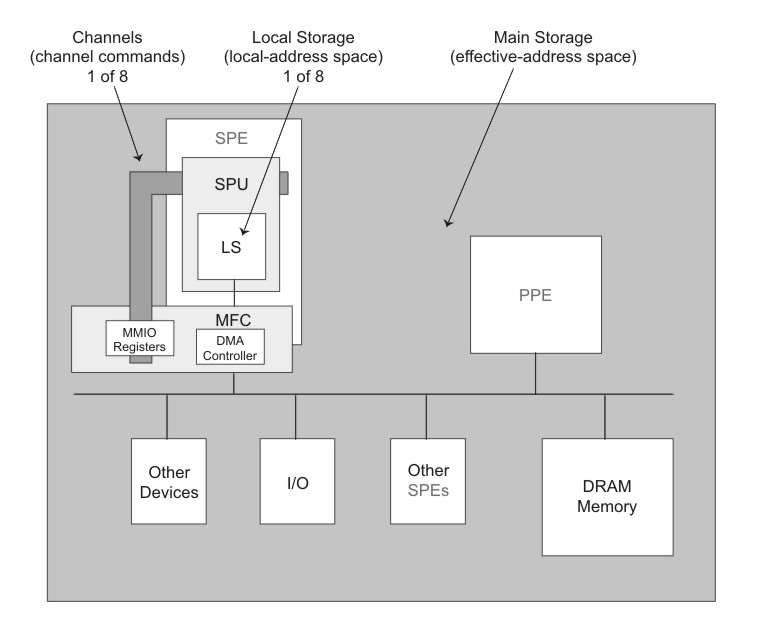
Three types of storage domains are defined in the Cell Broadband Engine: one main-storage domain , eight SPE local store domains , and eight SPE channel domains.
The three types of storage domains are shown in Figure 1. The main-storage domain, which is the entire effective-address space, can be configured by the PPE operating system to be shared by all processors and memory-mapped devices in the system (all I/O is memory-mapped).
However, the local-storage and channel problem-state (user-state) domains are private to the SPU, LS, and MFC of each SPE.
An SPE can only fetch instructions from its own LS, and loads and stores can only access the LS. An SPE or PPE performs data transfers between the SPE's LS and main storage primarily using DMA transfers controlled by the MFC DMA controller for that SPE. Software on the SPE's SPU interacts with the MFC through channels, which enqueue DMA commands and provide other facilities, such as mailboxes, signal notification, and access auxiliary resources.
An SPE program references its own LS using a Local Store Address (LSA). The LS of each SPE is also assigned a Real Address (RA) range within the system's memory map. This allows privileged software to map LS areas into the effective address (EA) space, where the PPE, other SPEs, and other devices that generate EAs can access the LS.
Each SPE's MFC serves as a data-transfer engine. DMA transfer requests contain both an LSA and an EA. Thus, they can address both an SPE's LS and main storage and thereby initiate DMA transfers between the domains. The MFC accomplishes this by maintaining and processing an MFC command queue. DMA requests can be sent to an MFC either by software on its associated SPU or on the PPE, or by any other processing device that has access to the MFC's MMIO problem-state registers.
The queued requests are converted into DMA transfers. Each MFC can maintain and process multiple in-progress DMA command requests and DMA transfers. The MFC can also autonomously manage a sequence of DMA transfers in response to a DMA-list command from its associated SPU. Each DMA command is tagged with a 5-bit Tag Group ID. Software can use this identifier to check or wait on the completion of all queued commands in one or more tag groups.
The MFC supports naturally aligned transfer sizes of 1, 2, 4, or 8 bytes, and multiples of 16-bytes, with a maximum transfer size of 16 KB. Peak performance can be achieved for transfers when both the EA and LSA are 128-byte aligned and the size of the transfer is a multiple of 128 bytes.
Each MFC has an associated memory management unit (MMU) that holds and processes address-translation and access-permission information supplied by the PPE operating system. This MMU is distinct from the one used by the PPE. To process an effective address provided by a DMA command, the MMU uses the same method as the PPE memory-management functions. Thus, DMA transfers are coherent with respect to system storage. Attributes of system storage are governed by the page and segment tables of the PowerPC Architecture.
| Name | Mnemonic | Max. Entries | R/W | Width (bits) |
|---|---|---|---|---|
| MFC Local-Storage Address | MFC_LSA | 1 | W | 32 |
| MFC Effective Address High | MFC_EAH | 1 | W | 32 |
| MFC Effective Address Low | MFC_EAL | 1 | W | 32 |
MFC Transfer Size |
MFC_Size |
1 | W | 32 |
| MFC Class ID and Command Opcode | MFC_ClassID_CMD | 8 | W | 32 |
| MFC Command Status | MFC_CMDStatus | 1 | R | 32 |
