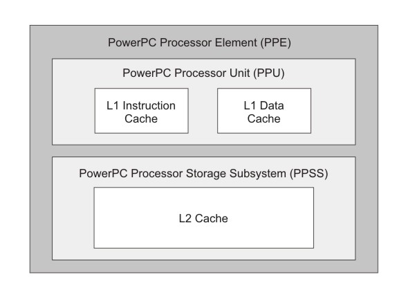
The PowerPC Processor Element (PPE) is a general-purpose, dual-threaded, 64-bit RISC processor that conforms to the PowerPC Architecture, version 2.02, with the Vector/SIMD Multimedia Extension.
Programs written for the PowerPC 970 processor, for example, should run on the Cell Broadband Engine without modification.
- The Power Processor Unit (PPU).
- The Power Processor Storage Subsystem (PPSS).
- the full set of 64-bit PowerPC registers,
- 32 128-bit vector registers,
- a 32-KB level 1 (L1) instruction cache,
- a 32-KB level 1 (L1) data cache,
- an instruction-control unit,
- a load and store unit,
- a fixed-point integer unit,
- a floating-point unit,
- a vector unit,
- a branch unit,
- a virtual-memory management unit.
The PPU supports two simultaneous threads of execution and can be viewed as a 2-way multiprocessor with shared dataflow. This appears to software as two independent processing units. The state for each thread is duplicated, including all architected and special-purpose registers except those that deal with system-level resources, such as logical partitions, memory, and thread-control. Most non-architected resources, such as caches and queues, are shared by both threads, except in cases where the resource is small or offers a critical performance improvement to multithreaded applications.
- a unified 512-KB level 2 (L2) instruction and data cache,
- various queues,
- a bus interface unit that handles bus arbitration and pacing on the EIB.
The L2 cache and the address-translation caches use replacement-management tables that allow software to control use of the caches. This software control over cache resources is especially useful for real-time programming.
